Table of Contents
In this tutorial, we will show how to build a world of objects with a dynamic, moving camera.
In the perspective projection tutorial, we defined a projection matrix that transforms objects from a specific camera space to clip-space. This camera space was defined primarily to make our perspective transformation as simple as possible. The camera itself sits immobile at the origin (0, 0, 0). The camera always looks down the Z axis, with objects that have a negative Z being considered in front of the camera.
All of the tutorials we have seen since then have had model transformations that go directly to camera space. While this functions, it is not as useful as it could be. Camera space is not a particularly flexible space. If we want to have a moving camera, obviously something needs to change.
We could modify our perspective matrix generation functions, so that we can project onto a camera that has an arbitrary position and orientation. But really, that's too much work; camera space itself works just fine for our needs. It would be easier to just introduce an additional transformation.
Right now, the problem is that we transform all of the objects from their individual model spaces to camera space directly. The only time the objects are in the same space relative to one another is when they are in camera space. So instead, we will introduce an intermediate space between model and camera space; let us call this space world space.
All objects will be transformed into world space. The camera itself will also have a particular position and orientation in world space. And since the camera has a known space, with a known position and orientation relative to world space, we have a transformation from world space to camera space. This also neatly explains why camera space is so named: it is the space where the world is expressed relative to the camera.
So, how do we define world space? Well, we defined model space by fiat: it's the space the vertex positions are in. Clip-space was defined for us. The only space thus far that we have had a real choice about is camera space. And we defined that in a way that gave us the simplest perspective projection matrix.
The last part gives us a hint. What defines a space is not the matrix that transforms to that space, but the matrix that transforms from that space. And this makes sense; a transformation matrix contains the basis vector and origin of the source space, as expressed in the destination coordinate system. Defining world space means defining the world-to-camera transform.
We can define this transform with a matrix. But something said earlier gives us a more user-friendly mechanism. We stated that one of the properties of world space is that the camera itself has a position and orientation in world space. That position and orientation, expressed in world space, comprises the camera-to-world transform; do note the order: “camera-to-world.” We want the opposite: world-to-camera.
The positioning is quite simple. Given the position of the camera in world space, the translation component of the world-to-camera matrix is the negation of that. This translates world space positions to be relative to the camera's position. So if the camera's position in world space is (3, 15, 4), then the translation component of the world-to-camera matrix is (-3, -15, -4).
The orientation is a bit more troublesome. There are many ways to express an orientation. In the last tutorial, we expressed it as a rotation about an axis. For a camera, it is much more natural to express the orientation relative to something more basic: a set of directions.
What a user most wants to do with a camera is look at something. So the direction that is dead center in camera space, that is directly along the -Z axis, is one direction vector. Another thing users want to do with cameras is rotate them around the viewing direction. So the second direction is the direction that is “up” in camera space. In camera space, the up direction is +Y.
We could specify a third direction, but that is unnecessary; it is implicit based on the other two and a single assumption. Because we want this to be a pure orientation matrix, the three basis vectors must be perpendicular to one another. Therefore, the third direction is the direction perpendicular to the other two. Of course, there are two vectors perpendicular to the two vectors. One goes left relative to the camera's orientation and the other goes right. By convention, we pick the direction that goes right.
So we define the camera's orientation (in world space) as being the viewing direction and the up direction. Oftentimes, a view direction is not the most useful way to orient a camera; it is often useful to select a point in world space to look at.
Therefore, we can define the camera-to-world (again, note the order) transform based on the camera's position in the world, a target point to look at in the world, and an up direction in the world. To get the world-to-camera transform, we need to expend some effort.
For the sake of reference, here is a diagram of the full transform for vertex positions, from the initial attribute loaded from the buffer object, to the final window-space position.

The tutorial project World Space demonstrates the use of a mobile camera in a world-space scene.
The controls for this tutorial are as follows:
Table 7.1. World Space Controls
| Function | Increase/Left | Decrease/Right |
|---|---|---|
| Move camera target up/down | E | Q |
| Move camera target horizontally | A | D |
| Move camera target vertically | W | S |
| Rotate camera horizontally around target | L | J |
| Rotate camera vertically around target | I | K |
| Move camera towards/away from target | U | O |
In addition, if you hold down the shift key while pressing any of these keys, then the affected control will be much slower. This allows for more precision movements. The spacebar will toggle the appearance of an object indicating the position of the camera point.
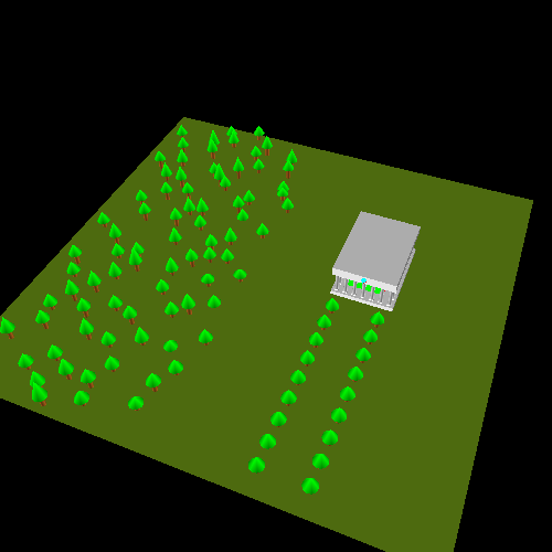
This world is more complicated than anything we've seen up until now. There are a lot of objects being rendered, and most of them are composed out of multiple objects.
This tutorial is the first to incorporate some of the features of the Unofficial
OpenGL SDK. Specifically, it uses the GL Util library's
glutil::MatrixStack class, which implements a matrix
stack very much like we saw in the last tutorial. The main difference is that we do
not use explicit push/pop functions. To push a matrix onto the stack, we instead use
a stack object, glutil::PushStack. The constructor pushes the
matrix and the destructor automatically pops it. This way, we can never stack
overflow or underflow.[4]
The tutorial also is the first to use the Framework's mesh class:
Framework::Mesh. It implements mesh loading from an
XML-based file format. We will discuss some of the functioning of this class in
detail in the next section. For now, let us say that this class's
Mesh::Render function is equivalent to binding a vertex
array object, rendering with one or more glDraw* calls, and
then unbinding the VAO. It expects a suitable program object to be bound to the
context.
Speaking of suitable program objects, this will be the first tutorial that uses more than one program object. This is the perfect time to bring up an important issue.
Separate programs do not share uniform locations. That is, if you call
glGetUniformLocation on one program object, it will not
necessarily return the same value from a different program object. This is
regardless of any other circumstance. You can declare the uniforms with the same
name, with the same types, in the same order, but OpenGL will not
guarantee that you get the same uniform locations. It
does not even guarantee that you get the same uniform locations on different
run-through of the same executable.
This means that uniform locations are local to a program object. Uniform data is also local to an object. For example:
Example 7.1. Window Resizing
void reshape (int w, int h)
{
    glutil::MatrixStack persMatrix;
    persMatrix.Perspective(45.0f, (w / (float)h), g_fzNear, g_fzFar);

    glUseProgram(UniformColor.theProgram);
    glUniformMatrix4fv(UniformColor.cameraToClipMatrixUnif, 1, GL_FALSE, glm::value_ptr(persMatrix.Top()));
    glUseProgram(ObjectColor.theProgram);
    glUniformMatrix4fv(ObjectColor.cameraToClipMatrixUnif, 1, GL_FALSE, glm::value_ptr(persMatrix.Top()));
    glUseProgram(UniformColorTint.theProgram);
    glUniformMatrix4fv(UniformColorTint.cameraToClipMatrixUnif, 1, GL_FALSE, glm::value_ptr(persMatrix.Top()));
    glUseProgram(0);

    glViewport(0, 0, (GLsizei) w, (GLsizei) h);
    glutPostRedisplay();
}
Here's our new function of the window reshaping function, using the
MatrixStack::Perspective function to generate the correct
perspective projection matrix. Notice that we must bind the 3 separate programs and
individually update each one's uniform for the camera-to-clip matrix.
Our three programs are made from 2 vertex shaders and 3 fragment shaders. The differences between these shaders is based on where they get their color information from.
We create three programs. One that expects a per-vertex color and uses that to write the fragment color. One that expects a per-vertex color and multiplies that with a uniform color to determine the fragment color. And one that does not take a per-vertex color; it simply uses the uniform color as the fragment's color. All of these do the same positional transformation, which is a series of three matrix multiplications:
Example 7.2. Position-only Vertex Shader
#version 330

layout(location = 0) in vec4 position;

uniform mat4 cameraToClipMatrix;
uniform mat4 worldToCameraMatrix;
uniform mat4 modelToWorldMatrix;

void main()
{
    vec4 temp = modelToWorldMatrix * position;
    temp = worldToCameraMatrix * temp;
    gl_Position = cameraToClipMatrix * temp;
}
The main rendering function implements the world-space and camera code. It begins by updating the world-to-camera matrix.
Example 7.3. Upload World to Camera Matrix
const glm::vec3 &camPos = ResolveCamPosition();

glutil::MatrixStack camMatrix;
camMatrix.SetMatrix(CalcLookAtMatrix(camPos, g_camTarget, glm::vec3(0.0f, 1.0f, 0.0f)));

glUseProgram(UniformColor.theProgram);
glUniformMatrix4fv(UniformColor.worldToCameraMatrixUnif, 1, GL_FALSE, glm::value_ptr(camMatrix.Top()));
glUseProgram(ObjectColor.theProgram);
glUniformMatrix4fv(ObjectColor.worldToCameraMatrixUnif, 1, GL_FALSE, glm::value_ptr(camMatrix.Top()));
glUseProgram(UniformColorTint.theProgram);
glUniformMatrix4fv(UniformColorTint.worldToCameraMatrixUnif, 1, GL_FALSE, glm::value_ptr(camMatrix.Top()));
glUseProgram(0);
The function ResolveCamPosition computes the camera position,
based on the user's input. CalcLookAtMatrix is the function
that takes a camera position in the world, a point in the world to look at, and an
up vector, and uses it to compute the world-to-camera matrix. We will look at that a
bit later.
Speaking of which, let's look at how ResolveCamPosition
works. The basic idea of this camera system is that there is a target point, which
is mobile. The camera's position is computed relative to this target point, so if
the target moves, the camera will follow it perfectly.
To do this, we use a special coordinate system trick. Instead of storing the relative position of the camera in a normal coordinate system, we instead use a spherical coordinate system, also known as polar coordinates.
Previously, we said that a coordinate system was defined by a series of vectors and an origin point. This was a useful simplification of the possibilities; this is true of any coordinate system that follows the rules of Euclidean geometry. Spherical coordinates (among many others) are non-Euclidean. For example, in Euclidean geometry, the sum of the angles of any triangle will add up to 180 degrees exactly. This is not true of spherical geometries or spherical coordinates. This is because “lines” in spherical geometries are curves when seen relative to Euclidean geometries.
Spherical coordinates are three dimensional, so they have 3 values. One value, commonly given the name “r” (for radius) represents the distance of the coordinate from the center of the coordinate system. This value is on the range [0, ∞). The second value, called “φ” (phi), represents the angle in the elliptical plane. This value extends on the range [0, 360). The third value, called “θ” (theta), represents the angle above and below the elliptical plane. This value is on the range [0, 180], where 0 means straight up and 180 means straight down.
This is much easier to see in diagram form:

This is a very convenient coordinate system for positioning an object around
another object, particularly if you want to move along spheres relative to another
object. The transformation from spherical coordinates back to Euclidean geometric
coordinates is implemented in ResolveCamPosition.
Example 7.4. Spherical to Euclidean Transform
glm::vec3 ResolveCamPosition()
{
    glutil::MatrixStack tempMat;

    float phi = Framework::DegToRad(g_sphereCamRelPos.x);
    float theta = Framework::DegToRad(g_sphereCamRelPos.y + 90.0f);

    float fSinTheta = sinf(theta);
    float fCosTheta = cosf(theta);
    float fCosPhi = cosf(phi);
    float fSinPhi = sinf(phi);

    glm::vec3 dirToCamera(fSinTheta * fCosPhi, fCosTheta, fSinTheta * fSinPhi);
    return (dirToCamera * g_sphereCamRelPos.z) + g_camTarget;
}
The global variable g_sphereCamRelPos contains the spherical
coordinates. The X value contains φ, the Y value contains θ, and the Z value is the
radius.
The Theta value used in our spherical coordinates is slightly different from the usual. Instead of being on the range [0, 180], it is on the range [-90, 90]; this is why there is an addition by 90 degrees before computing the Theta angle in radians.
The dirToCamera is just a direction vector. Only by scaling it
by the radius (g_sphereCamRelPos.z) do we get the full
decomposition from spherical coordinates to Euclidean. Applying the camera target as
an offset is what keeps the camera's position relative to the target.
All of the above simply gets us a position for the camera and a location where the
camera is looking. The matrix is computed by feeding these values into
CalcLookAtMatrix. It takes a position for the camera, a
point in the world that the camera should be looking in, and a direction in
world-space that should be considered “up” based on where the camera is
looking.
The implementation of this function is non-trivial. We will not go into detail explaining how it works, as it involves a lot of complex math concepts that have not been introduced. Using the function is is much easier than understanding how it works. Even so, there is one major caveat with this function (and any function of the like).
It is very important that the “up” direction is not along the same line as the direction from the camera position to the look at target. If up is very close to that direction then the generated matrix is no longer valid and unpleasant things will happen.
Since it does not make physical sense for “up” to be directly behind or in front of the viewer, it makes a degree of sense that this would likewise produce a nonsensical matrix. This problem usually crops up in camera systems like the one devised here, where the camera is facing a certain point and is rotating around that point, without rotating the up direction at the same time. In the case of this code, the up/down angle is clamped to never get high enough to cause a problem.
Once the camera matrix is computed, it is farmed out to each of the programs. After that, rendering is pretty simple.
The meshes we have loaded for this tutorial are unit sized. That is, they are one unit across in their major axes. They also are usually centered at the origin in their local coordinate system. This make it easy to scale them to arbitrary sizes for any particular use.
The ground is based on the unit plane mesh. This is just a square with the sides being unit length. This is rendered by the following code:
Example 7.5. Draw the Ground
glutil::PushStack push(modelMatrix);

modelMatrix.Scale(glm::vec3(100.0f, 1.0f, 100.0f));

glUseProgram(UniformColor.theProgram);
glUniformMatrix4fv(UniformColor.modelToWorldMatrixUnif, 1, GL_FALSE, glm::value_ptr(modelMatrix.Top()));
glUniform4f(UniformColor.baseColorUnif, 0.302f, 0.416f, 0.0589f, 1.0f);
g_pPlaneMesh->Render();
glUseProgram(0);
The unit plane mesh has no color attribute, so we use the
UniformColor program. We apply a scale matrix to the model
stack, so that the 1x1 plane becomes 100x100 in size. After setting the color, the
plane is rendered.
All of the trees are drawn from the DrawForest
function.
Example 7.6. DrawForest Function
void DrawForest(glutil::MatrixStack &modelMatrix)
{
    for(int iTree = 0; iTree < ARRAY_COUNT(g_forest); iTree++)
    {
        const TreeData &currTree = g_forest[iTree];

        glutil::PushStack push(modelMatrix);
        modelMatrix.Translate(glm::vec3(currTree.fXPos, 0.0f, currTree.fZPos));
        DrawTree(modelMatrix, currTree.fTrunkHeight, currTree.fConeHeight);
    }
}
This function iterates over a large table and draws a tree for each element in
that table. The table entries determine where in world space the tree is drawn and
how tall it is. The location is stored as a translation in the matrix stack (after
pushing), and the tree attributes are passed to the DrawTree
function to render.
The Parthenon is drawn from the DrawParthenon function. Since
this draw function, like DrawTree, expects the matrix stack to
transform it to its world-space position, the first step we see is applying a
translation matrix to the stack.
Example 7.7. Call to DrawParthenon
glutil::PushStack push(modelMatrix);
modelMatrix.Translate(glm::vec3(20.0f, 0.0f, -10.0f));

DrawParthenon(modelMatrix);
The actual DrawParthenon function is pretty simple. It uses
DrawColumn to draw all of the columns at the various
locations around the building. It draws scaled cubes for the base and ceiling, and
uses the colored version of the cube for the headpiece at the front and the interior
of the building. Columns are scaled cubes and cylinders.
The last part of the display function is more interesting.
Pressing the Spacebar toggles the drawing of a representation of
the camera target point. Here is how it gets drawn:
Example 7.8. Draw Camera Target
glDisable(GL_DEPTH_TEST);
glm::mat4 idenity(1.0f);

glutil::PushStack push(modelMatrix);

glm::vec3 cameraAimVec = g_camTarget - camPos;
modelMatrix.Translate(0.0f, 0.0, -glm::length(cameraAimVec));
modelMatrix.Scale(1.0f, 1.0f, 1.0f);

glUseProgram(ObjectColor.theProgram);
glUniformMatrix4fv(ObjectColor.modelToWorldMatrixUnif, 1, GL_FALSE,
    glm::value_ptr(modelMatrix.Top()));
glUniformMatrix4fv(ObjectColor.worldToCameraMatrixUnif, 1, GL_FALSE,
    glm::value_ptr(idenity));
g_pCubeColorMesh->Render();
glUseProgram(0);
glEnable(GL_DEPTH_TEST);
The first thing that happens is that the depth test is turned off. This means that the camera target point will always be seen, no matter where it is. So if you move the target point inside the building or a tree, you will still see it. This is a useful technique for UI-type objects like this.
The next important thing is that the world-to-camera matrix is set to identity. This means that the model-to-world matrix functions as a model-to-camera matrix. We are going back to positioning objects in front of the camera, which is what we actually want. The cube is translated down the -Z axis, which positions it directly in front of the camera. It positions the square at the same distance from the camera as the camera would be from the target point.
For the last few tutorials, we have been building up a transformation framework and hierarchy. Model space to world space to camera space to clip space. But the important thing to remember is that this framework is only useful to you if it does what you want. If you need to position an object directly in front of the camera, then simply remove world space from the equation entirely and deal directly with camera space.
We could even turn the depth test back on, and the camera target would interact correctly with the rest of the world. It is a part of the world, even though it seems like it goes through a different transform pipe.
Indeed, you could render part of a scene with one perspective matrix and part with another. This is a common technique for first-person shooter games. The main world is rendered with one perspective, and the part of the first-person character that is visible is rendered with another matrix.
Do not get so caught up in “the way things ought to be done” that you forget what you could have done if you broke free of the framework. Never hold so tightly to one way of doing something that it prevents you from seeing how to do something you need to much easier. For example, we could have applied the reverse of the camera matrix to the model-to-world matrix. Or we could just get rid of that matrix altogether and make everything work very easily and simply.
[4] This technique, using constructors and destructors to do this kind of scope-bounded work, is called Resource Acquisition Is Initialization (RAII). It is a common C++ resource management technique. You can find more information about it online. If you are unfamiliar with it, I suggest you become familiar with it.