Our perfect sphere looks pretty nice. It has no polygonal outlines and you can zoom in on it forever. However, it is unfortunately very wrong.
To see how, toggle back to rendering the mesh on sphere 1 (the central blue one). Then move the camera so that the sphere is at the left edge of the screen. Then toggle back to impostor rendering.
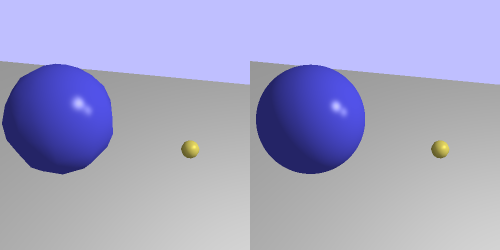
What's going on here? The mesh sphere seems to be wider than the impostor sphere. This must mean that the mesh sphere is doing something our impostor is not. Does this have to do with the inaccuracy of the mesh sphere?
Quite the opposite, in fact. The mesh sphere is correct. The problem is that our impostor is too simple.
Look back at how we did our computations. We map a sphere down to a flat surface. The problem is that “down” in this case is in the camera-space Z direction. The mapping between the surface and the sphere is static; it does not change based on the viewing angle.
Consider this 2D case:
The dark line through the circle represents the square we drew. When viewing the sphere off to the side like this, we should not be able to see the left-edge of the sphere facing perpendicular to the camera. And we should see some of the sphere on the right that is behind the plane.
So how do we solve this?
Use better math. Our last algorithm is a decent approximation if the spheres are somewhat small. But if the spheres are reasonably large (which also can mean close to the camera), then our approximation is shown to be very fake. Our new algorithm needs to take this into account.
This algorithm is based on a term you may have heard before: ray tracing. We will not be implementing a full ray tracing algorithm here; instead, we will use it solely to get the position and normal of a sphere at a certain point.
A ray is a direction and a position; it represents a line extending from the position along that direction. The points on the ray can be expressed as the following equation:

The t value can be positive or negative, but for our needs, we'll
stick with positive values.
For each fragment, we want to create a ray from the camera position in the direction towards that point on the impostor square. Then we want to detect the point on the sphere that it hits, if any. If the ray intersects the sphere, then we use that point and normal for our lighting equation.
The math for this is fairly simple. The equation for the points on a sphere is this:

For any point P, if this equation is true, if the length between that point and the sphere's center equals the radius, then P is on the sphere. So we can substitute our ray equation for P:

Our ray goes from the camera into the scene. Since we're in camera space, the camera
is at the origin. So O can be eliminated from the equation. To solve for
t, we need to get rid of that length. One way to do it is to
re-express the sphere equation as the length squared. So then we get:

The square of the length of a vector is the same as that vector dot-producted with itself. So let's do that:

The dot product is distributive. Indeed, it follows most of the rules of scalar multiplication. This gives us:

While this equation has a lot of vector elements in it, as far as t is concerned, it is a scalar equation. Indeed, it is a quadratic equation, with respect to t. Ah, good old algebra.

In case you've forgotten, the part under the square root in the quadratic formula is called the discriminant. If this value is negative, then the equation has no solution. In terms of our ray test, this means the ray misses the sphere.
As you may recall, the square root can be either positive or negative. This gives us two t values. Which makes sense; the ray hits the sphere in two places: once going in, and once coming out. The correct t value that we're interested in is the smallest one. Once we have that, we can use the ray equation to compute the point. With the point and the center of the sphere, we can compute the normal. And we're back in business.
To see this done, open up the last tutorial project. Since they use the exact same source, and since they use the same uniforms and other interfaces for their shaders, there was no need to make another code project for it. To see the ray-traced version, press the J key; all impostors will use the perspective version. To go back to the flat version, press L.
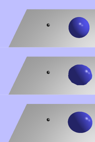
The top is the original impostor, the middle is the actual mesh, and the bottom is our new ray traced impostor.
The Impostor function in the new fragment shader implements
our ray tracing algorithm. More important than this are the changes to the vertex
shader's computation of the impostor square:
Example 13.3. Ray Traced Impostor Square
const float g_boxCorrection = 1.5;

void main()
{
    vec2 offset;
    switch(gl_VertexID)
    {
    case 0:
        //Bottom-left
        mapping = vec2(-1.0, -1.0) * g_boxCorrection;
        offset = vec2(-sphereRadius, -sphereRadius);
        break;
    case 1:
        //Top-left
        mapping = vec2(-1.0, 1.0) * g_boxCorrection;
        offset = vec2(-sphereRadius, sphereRadius);
        break;
    case 2:
        //Bottom-right
        mapping = vec2(1.0, -1.0) * g_boxCorrection;
        offset = vec2(sphereRadius, -sphereRadius);
        break;
    case 3:
        //Top-right
        mapping = vec2(1.0, 1.0) * g_boxCorrection;
        offset = vec2(sphereRadius, sphereRadius);
        break;
    }

    vec4 cameraCornerPos = vec4(cameraSpherePos, 1.0);
    cameraCornerPos.xy += offset * g_boxCorrection;

    gl_Position = cameraToClipMatrix * cameraCornerPos;
}
We have expanded the size of the square by 50%. What is the purpose of this? Well, let's look at our 2D image again.

The black line represents the square we used originally. There is a portion to the left of the projection that we should be able to see. However, with proper ray tracing, it would not fit onto the area of the radius-sized square.
This means that we need to expand the size of the square. Rather than finding a clever way to compute the exact extent of the sphere's area projected onto a square, it's much easier to just make the square bigger. This is even moreso considering that such math would have to take into account things like the viewport and the perspective matrix. Sure, we will end up running the rasterizer rather more than strictly necessary. But it's overall much simpler.